WSW Technological Knowledge: Processing Technology Analysis of New Cage Hole of Cylindrical Roller Bearing
Processing the new cage hole of cylindrical roller bearing by manual programming

Abstract: This paper analyzes the machining characteristics and process feasibility of the new cage hole of cylindrical roller bearing, designs the machining process method, and realizes the machining of the new cage through manual programming.
Key words: cylindrical roller bearing; Cage; 3D surface; Process analysis
1 Cage structure
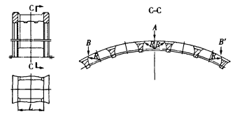
The new cage of cylindrical roller bearing is an integral structure cage, as shown in Figure 1. The processing of cylindrical roller bearing cage hole is generally to process pocket hole in the axial direction of cage or square hole in the radial direction, which belongs to the processing of two-dimensional curved surface. The new cage is processed into a cylindrical curved surface in the radial direction of the cage (Fig. 1), which belongs to a three-dimensional surface. The cylindrical curved surface needs to be processed in two times, that is, one half cylindrical 3D surface is processed, and then the other half cylindrical 3D surface is processed.

Figure 1 cage structure
2 Process feasibility analysis
2.1 Processing feasibility analysis
Ordinary boring machines and milling machines can only process two-dimensional surfaces in the cutting process, and cannot realize the processing of three-dimensional surfaces. Therefore, the drilling and milling machining center is selected to process the three-dimensional surface. The numerical control device of the drilling and milling machining center can control two or more axes at the same time, strictly and continuously control the machining position and speed, and has the functions of linear and circular interpolation, tool compensation and mirror image. Therefore, the four axis three linkage vertical machining center can be used to process this three-dimensional curved surface.
2.2 Tool selection and interference analysis
For three-dimensional curved surface, the best choice of cutter is spherical end milling cutter. Because the spherical end milling is used to process three-dimensional surfaces, as long as the ball center of the spherical cutter is located on the equidistant surface of the machined surface, the required surface shape can be milled regardless of the arrangement of the cutter route and cutter axis direction. The spherical end milling cutter is used to clamp and process the three-dimensional surface on the four axis three linkage machining center at one time. Although the cutter center is constrained on the equal distance of the machining curvature, the axial direction of the milling cutter can be determined according to the shape of the surface and the shape and position of the constraint, but the z-axis direction must be monotonous (that is, the z-axis is always perpendicular to the partner plane) to realize the machining. The z-axis of the four axis three linkage vertical machining center is monotonous, so machining can be realized.
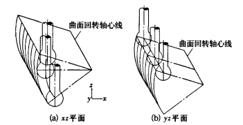
In order to avoid interference in the process of machining three-dimensional surfaces with spherical end mills, the radius of the spherical cutter must be less than the minimum radius of curvature of the surface recess. Therefore, in the process design, we should analyze the minimum concave curvature radius of the whole surface to be machined, and take this as the basis for the selection of tool radius. However, when the surface has a small concave curvature radius, it cannot be processed with a small tool because of possible interference. The reasonable method is to first use a large spherical end mill for machining, and then carry out subsequent treatment on the concave and sharp corners. After selecting the tool radius, the machining position of the three-dimensional surface can be determined according to the graphic size. It can be seen from Figure 1 that when machining three-dimensional surfaces at B and B ', the tool will not interfere. Through the analysis of tool selection and interference, the tool path in the two machining planes can be determined, as shown in Figure 2.

Figure 2 tool path
According to the above process analysis, the processing procedure of cylindrical three-dimensional curved surface is determined as follows: rough drilling → square hole milling → three-dimensional curved surface milling → four corner root cleaning of three-dimensional curved surface.
3 Analysis of manual programming implementation
For 3D surface, automatic programming is the most reasonable choice. In the absence of automatic programming software, the machining of 3D surface can only be realized by manual programming. However, not all three-dimensional surfaces can be realized by manual programming, such as complex guide surfaces, blade surfaces, etc. their curves are not single curves. When programming, the starting and ending coordinates of each curve inflection point need to be given, which is too difficult to calculate manually. The three-dimensional curved surface of the cage is a cylindrical surface, and its curve is a single arc curve. Therefore, manual programming can be realized as long as the starting and ending coordinates of the arc are given.
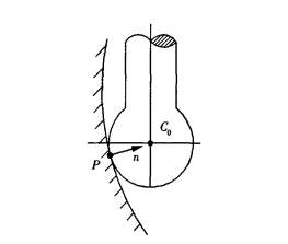
First, calculate the starting point coordinates and end point coordinates of the tool point. The relationship between the tool and the machined surface is shown in Figure 3. The spherical tool location is tool center C0. The accurate position of the tool in the workpiece coordinate system can be described by tool location and tool axis vector. The tool center coordinate (0, 0, 0) and its tool axis vector coordinate (0, 0, 1) are fixed. The calculation formula of tool center point vector of any point P on the milling surface of spherical cutter is:

Fig. 3 Relationship between tool and machined surface
rC0=rP+Rn (1)
Where rC0 is the point vector of the knife center; rPis the point vector of contact P on the machined surface; R is the tool radius; It is the unit normal vector at point P of the machined surface.
From Figure 3 and equation (1), it can be seen that the ball center of the spherical cutter is located on the equidistant surface of the machining surface, and the distance is the cutter radius R. write equation (1) as the component form as follows:
xC0=xp+Rnx
YC0=yp+Rny
zC0=z+Rnz
Through formula (2), the starting point coordinates and the end point coordinates of the tool location can be obtained respectively.
From the processing technology of the three-dimensional curved surface of the new cage, it can be seen that the rough drilling hole L and the milling hole L are two-dimensional processing, and manual programming is easy to realize at point a in Figure 1. The milling of three-dimensional curved surface and the root cleaning of four corners are three-dimensional curved surface machining. According to the machining process size, the starting point coordinates and end point coordinates of the tool location can be calculated respectively, and then manual programming can be realized.
It can be seen from the tool path in Figure 2 that there are two kinds of programming: one is on the xz plane (Figure 2a); The other is on the yz plane (Fig. 2b). The operator can choose any processing plane, manually arrange half of the three-dimensional surface program, and then realize the arrangement of the other half of the three-dimensional surface program through the mirror function.
4 Conclusion
This new type of cage is trial produced on the four axis three linkage vertical machining center. All the machining dimensions and accuracy of its hole meet the design requirements, and the bearing test effect is good.
More about WSW Spherical Roller Bearings:
A spherical roller bearing is a rolling-element bearing that permits rotation with low friction, and permits angular misalignment. Typically these bearings support a rotating shaft in the bore of the inner ring that may be misaligned in respect to the outer ring. The misalignment is possible due to the spherical internal shape of the outer ring and spherical rollers.

WSW is located at Wafangdian City, in the north of Dalian City, Liaoning Province, which is famous for the birthplace of China industrial bearing and China Bearing City. The convenient traffic condition and superior economic environment and stable political situation provide bearing with a good trade platform to the world. WSW is a comprehensive enterprise, which is a collection of bearing D&R, production and selling, and has passed ISO9001-2000 quality management system certification.
Now WSW can produce various types of bearings, over 200 series and 5,000 designations or so. For example, deep groove ball bearings, spherical ball bearings, cylindrical roller bearings, self alining roller bearings, angular contact ball bearings, tapered roller bearings, thrust ball bearings, thrust roller bearings, spherical plain bearings, car hub bearings, slewing bearings and British series bearings and so on. It can also design and produce various types of non-standard bearings according to customers’ different requirement. Products are widely used in metallurgy, mining, petroleum, chemical industry, machinery, vehicles, paper making, cement industries etc, and exported to Europe, USA and South Asia market and gained customers’ recognition at home and abroad.
We promise that WSW only provides excellent quality products with the best price and the most professional service! We sincerely invite all of you to cooperate with us.

